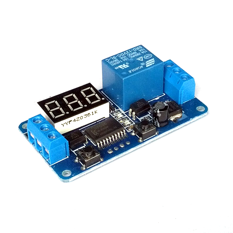
Time Delay Relay Module - 12V, Adjustable Timer
This is a single 12V relay module with a time delay circuit.
How this module works:
When triggered, the relay switches for a specified duration (as shown on the display) and then goes back to the original state after that. This relay module operates on 12V with an adjustable timer that can be set from 0 to 999 seconds.
The board has two 3-wire terminals on each end. One set is connected to the relay. If you look at the back, you will see CB, COM, and CK. The CB is the relay terminal that is "NC" - normally connected to the COM. The CK is the relay terminal that "NO" - normally open i.e. not connected to the COM. The COM is the relay common terminal. When the relay is triggered, the COM will be connected to the CK connector and it stays that way during timer operation.
The other set of terminal is the power and control, labeled GND, IN, and VCC at the back. This module is powered by 12V DC, applied to the VCC and GND. When powered, the board lights up with a red led power indicator on the board and the 3 digit numeric display. The IN connector is for trigger input. This is a HIGH trigger relay. When a positive 12V DC is applied to the IN connector, the timer starts counting down from the number shown on the display.
How to set the timer:
Apply power to the relay (GND and VCC) and you will see the display lights up. Use the two push button on-board to set the timer. The right button increases the digit from 0 to 9. The left button cycles through each digit. This setting will remain even after the power is removed.
Tips: Use two of this module to create a device which control ON and OFF for two different time duration back and forth. For example, ON for 10 seconds then OFF for 20 seconds and then ON back for 10 seconds and so on. To do this, just route a wire from first board IN to second board CB and route another wire from second board IN to first board CB.
Technical details:
- Single 12V relay with optocoupler. Active HIGH trigger. Can be triggered by external signal
- LED timer display from 999 to 0 seconds. LED changes each second. 0.01% error per second
- Board dimension: 65 x 35 mm
