Tilt Sensor Module - Digital Output
Tilt sensor detect orientation or inclination. They can be found in game controllers, toys, cameras, robotic applications, navigation systems and many more.
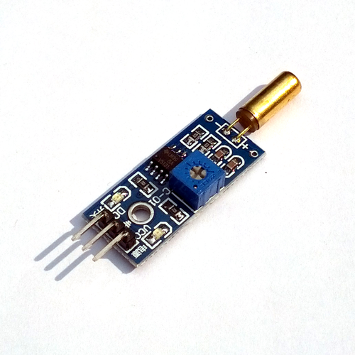
This is a basic tilt sensor board. The sensor itself is the SW-520D roll ball switch. It is a tube with a pair of tiny metal ball that act like a switch. When the sensor is in upright position, the balls making connection between the two contacts that connect the sensor to the board. When the sensor is tilted, the balls roll and break the contact.
The board has a LM393 voltage comparator chip to give out digital output and a potentiometer for sensor sensitivity adjustment. The working voltage of this module is between 3.3V and 5V. There are three pins for output marked as VCC, Ground and DO.
The DO pin gives digital output and you can read it easily with any microcontroller/microprocessor. When the sensor is upright (not tilted), the DO pin gives output LOW and when the sensor is tilted beyond the threshold angle, it gives output HIGH. The threshold angle is around 45 degree from the upright position.
There are 2 status indicator LEDs on board. The red one is to tell us the power is connected and the green one is to indicate that the sensor is tilted or not. There is also a mounting hole on the PCB so that you can fix the position of this module.
Technical details:
- Highly sensitive SW-520D tilt sensor
- Operating voltage: 3.3V - 5V
- Red LED - operational status indicator
- Green LED - output status indicator
- Green LED ON, output LOW
- Green LED OFF, output HIGH
- A potentiometer that can be used to adjust sensitivity
- Output format: Digital (HIGH and LOW)
- Board dimension: 32mm x 14mm

