T-shape GPIO Breakout Kit for Raspberry Pi
GPIO pins allow you to connect your Pi to external electronic devices such as display LCDs, servo motor, GPS and many more. Usually, a breadboard is used for easy prototyping with these devices.
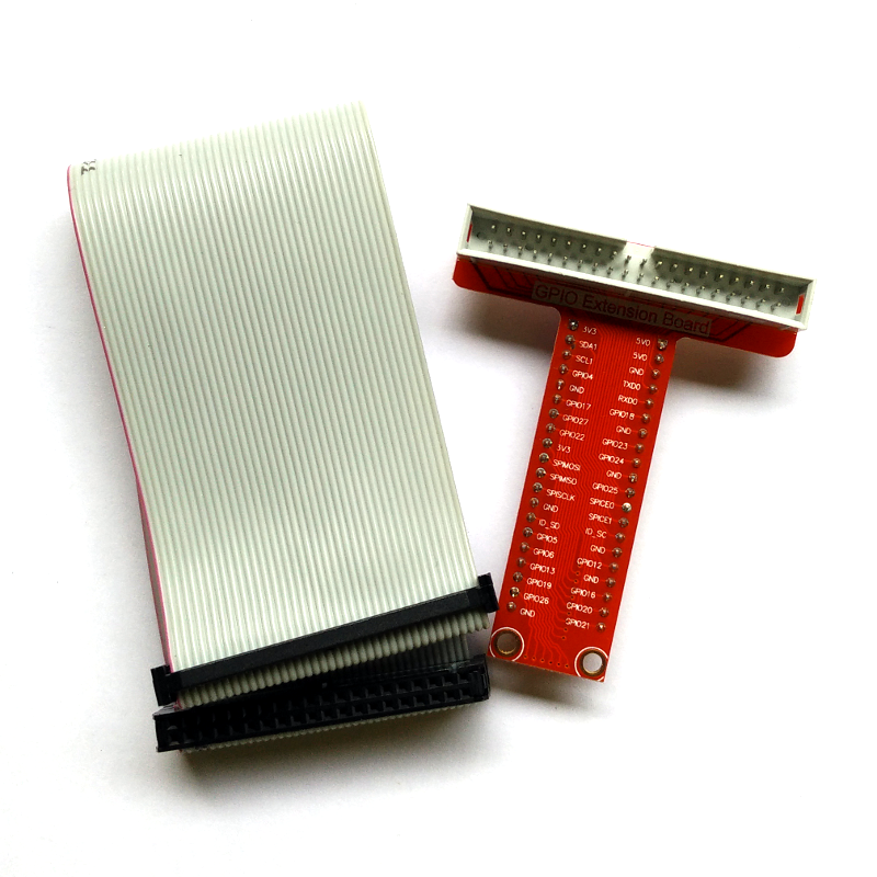
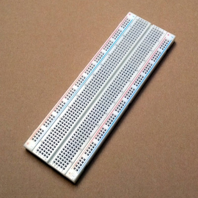
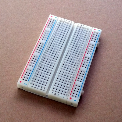
But then, wiring the GPIO pins directly to a breadboard is not easy. This is where this kit comes in handy. It allows you to break the 40-pin GPIO header onto a solderless breadboard. The connection pins are marked on the PCB for quick reference. You no longer have to refer to pin-out diagram when making connection. Accessing GPIO pins have never been easier!
This breakout kit has 2 main pieces. It has a 40-pin ribbon cable with socket that can be attached to Raspberry Pi GPIO pins and a T-shape PCB where you attach the other end of the ribbon cable. Pin 1 is marked with a red stripe. It's a best practice to connect the red stripe of the cable to the Pin 1 (near J8 mark) on the board. Be sure to follow this convention when connecting the cable avoid the risk of damaging your Pi.
This PCB is then can be plugged onto a breadboard. The PCB is printed with information about which GPIO pins that you are connecting to for quick and easy reference. You no longer have to refer to pin-out diagram when making connection.
This product is not compatible with the old Model A or B with 26 GPIO pin.
Package contents:
- 40-way ribbon cable with IDC connectors
- T-Shape GPIO breakout board
Features:
- Fully assembled T-shape breakout board; no soldering required!
- Compatible with all Raspberry Pi models (with 40 GPIO pin)
- The the pin connections are marked on the PCB
Related links:


