Categories
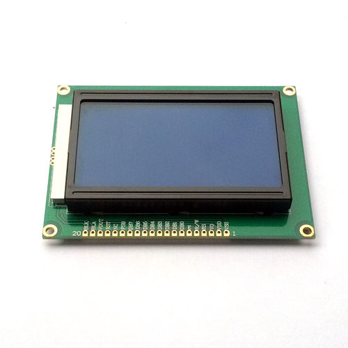
LCD Module LM 12864 128x64 Dots Graphic - 3.3V, blue backlight
RM47.00
1
Save this product for later
LCD Module LM 12864 128x64 Dots Graphic - 3.3V, blue backlight
Product Details
This is a 128 x 64 dots graphic LCD module. It runs on 3.3V with white dots on blue backlight.
A 20-pin header is included.
Specifications:
- Display: 128 x 64 dots (graphic)
- Power supply voltage: 3.3V
- Controller: ST7920/ST7921
- Interface: Parallel/SPI (20-pin contact)
- Backlight colour: Blue
- Character colour: White
- Dimension: 93 x 70 x 13.5 mm
Pin Out:
| PIN NO. | SYMBOL | DESCRIPTION | FUNCTION |
|---|---|---|---|
| 1 | VSS | Ground | 0V (GND) |
| 2 | VDD | Power Supply For Logic Circuit | +3.3V |
| 3 | V0 | LCD Contrast Adjustment | |
| 4 | RS or CS | Parallel Mode: Instruction/Data Register Selection Serial Mode: Chip Select |
Parallel Mode: RS = 0 : Instruction Register RS = 1 : Data Register Serial Mode: Active-high |
| 5 | R/W or SID | Parallel Mode: Read/Write Selection Serial Mode: Data |
Parallel Mode: R/W = 0 : Register Write R/W = 1 : Register Read |
| 6 | E or SCK | Parallel Mode: Enable Signal Serial Mode: Clock |
Parallel Mode: Active-high |
| 7 | DB0 | Parallel Mode: Data Bus Serial Mode: NC |
Parallel Mode: DB0-DB7 |
| 8 | DB1 | ||
| 9 | DB2 | ||
| 10 | DB3 | ||
| 11 | DB4 | ||
| 12 | DB5 | ||
| 13 | DB6 | ||
| 14 | DB7 | ||
| 15 | PSB | Serial/Parallel Selection | PSB=0 : Serial Mode PSB=1 : 8/4Bit Parallel Bus Mode |
| 16 | NC | ||
| 17 | RST | Reset Signal | Active-low RSTB=0,Display Off, Display From Line 0 |
| 18 | Vout | Dual Voltage Output | Available when VDD=+3.3V |
| 19 | A | Supply Voltage For LED+ | +3.3V |
| 20 | K | Supply Voltage For LED- | 0V |
Display prices in:MYR
