A microcontroller has a limited power output (current and voltage). Motors usually draws a larger current than what a microcontroller can safely provide. This is where a driver/controller module comes in. It able to provide enough current to drive motors and the same time allows a microcontroller/microcomputer to decide regarding the speed and the direction of the motors.
This module uses L298N chip as its main driver. It features a dual H-bridge motor controller that can drive two DC motors independently at a time. Alternatively, it can also drive one 4-wire stepper motor. The module runs on two circuit. One can work on high voltage up to 35V. It uses the input voltage to drive the motors. The other one runs on lower 5V for the module logic control. This can be interfaced to a microcontroller for a logic level signal control. There is a 78M05 regulator chip on board that can take the main input voltage and provide 5V power supply for the logic circuit. To avoid damage to the 78M05, if you are using more than 12V to drive the motor, it is better if you can provide an external 5V for the logic power supply.
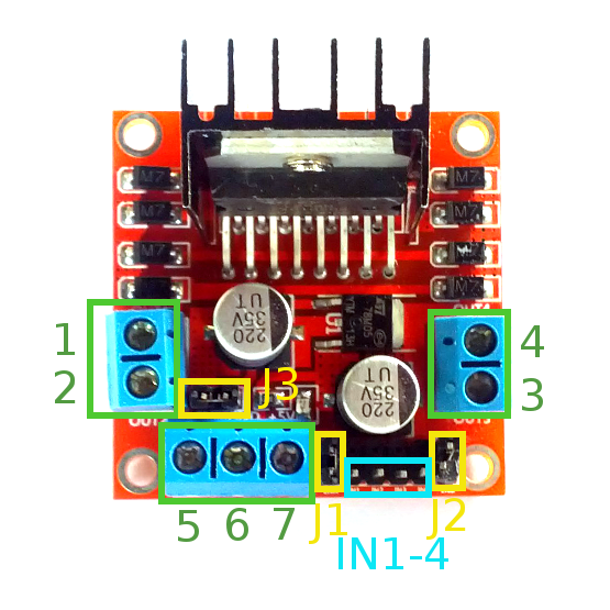
Board layout
Screw terminal 1 and 2 - Output to Motor A, connect to motor terminal
Screw terminal 3 and 4 - Output to Motor B, connect to motor terminal
Screw terminal 5 - Input voltage (5V-35V recommended)
Screw terminal 6 - GND, common ground for power supply and microcontroller
Screw terminal 7 - Provide +5V power supply if input voltage is in between 7V-12V, can be used to power microcontroller or some other components
Jumper J1 - Enable Motor A, place jumper on to enable, remove jumper to disable
Jumper J2 - Enable Motor B, place jumper to on enable, remove jumper to disable
Jumper J3 - Enable on-board 5V logical power supply. If your input power supply is outside of 7V-12V range, remove this jumper and provide 5V externally to terminal 7
Pin IN1-4 - Control pins that control the direction of the motors, connect to microcontroller
A heatsink is attached to the LN298N chip for better heat dissipation.
Usage:
The module ships with three jumpers on J1, J2 and J3. In most scenarios, you would want to leave these jumpers on
When jumper J1 is enabled, signal from microcontroller to IN1 and IN2 controls the direction of DC Motor A (connected to output 1 and 2). When both IN1 and IN2 are set the same (either HIGH or LOW), the motor doesn't move. When one is set HIGH and the other is set LOW, the motor moves in one direction. To reverse the direction of the motor, just reverse the signal to IN1 and IN2
Same as above, when J2 is enabled, IN3 and IN4 controls the direction of DC Motor B (connected to output 3 and 4)
It is safe to connect IN1-IN4 to a 3.3V or 5V microcontroller/microcomputer pin. Do not connect other 5V pin to a 3.3V system.
Terminal 5 is for input voltage that will drive the motor (motor power supply). Check your motor spec for the suitable voltage. The recommended range is between 5V-35V
Terminal 6 is for common ground. Remember to connect ground from both power and microcontroller here
There is an on-board 78M05 regulator chip that can take input power supply and regulate it down to 5V for logic power supply. Terminal 7 gives a +5V supply output when input voltage between 7V-12V is applied. In this case, you can use the 5V at terminal 7 to power your microcontroller (or other external components) so that only one power supply is required. Do not connect input voltage here
If you happen to use input voltage outside of the 7V-12V range, remove J3 jumper and provide external 5V logical power supply to terminal 7. So now you have to provide two external power supply. One is for driving the motor, the other is for driving the logic

