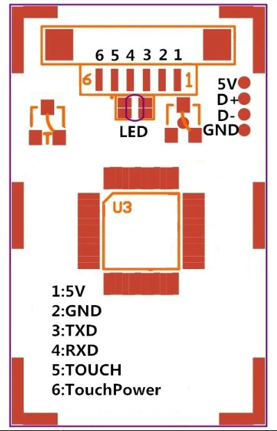
This module is now upgraded with additional finger detection signal. There is a 6-pin socket on board instead of a 4-pin socket on the previous model.
Fingerprint recognition is one of the most popular form of biometrics used to verify the identity of individuals. A fingerprint sensor is used to capture the digital image of a fingerprint pattern. It typically captures the fingerprint image, extracting the unique features of the fingerprint and storing a digital template at the time of enrolment and later comparing new image against the stored fingerprint template for verification.
An capacitive fingerprint sensor uses electrical current instead of light. Internally, it has an array of tiny capacitor plates to capture the image of a fingerprint. This type of fingerprint sensor is typically used in consumer electronic device such as a laptop or a mobile phone. They are relatively compact and uses low power. However, they are more susceptible to damage in the long run compared to the optical fingerprint sensor.
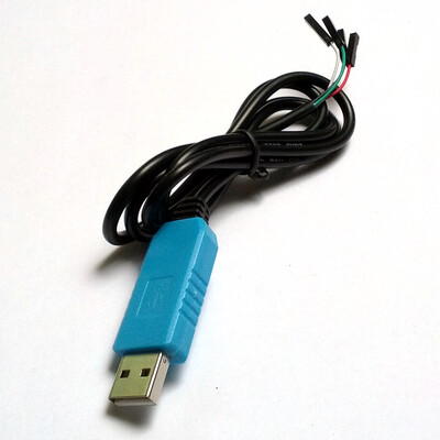
This particular model of fingerprint sensor uses serial TTL logic for communication via a 6-pin socket (VCC, GND, TD, RD, Touch signal, Touch power) on the circuit board. A 6-pin wire harness is included. You can use popular development boards such as Raspberry Pi or Arduino as a controller. You can also connect it to a PC with a TTL to USB converter such as the PL2303TA cable. You can use the Windows demo software that will be provided to test the module, enroll fingerprints and see an image of your fingerprint.
This board now comes with finger detection signal feature. This feature wakes up the module upon the placement of a finger to conserve power which is great especially for battery powered application. The finger detection power pin must always be connected to 3.3V-5V. The current consumption of this function is around 5 uA only.
Technical details:
Power DC : 4.2V-6.0V
Interface : Serial UART (TTL logical level 3.3V) / USB 2.0
Working current
Typical: 40mA
Peak: 50mA
Matching Mode: 1:1 (one-to-one) and 1:N (one-to-many)


