ESP8266 ESP-12F is an enhanced version of ESP-12E WiFi microcontroller module with a new antenna revision for better RF performance. It comes with PCB antenna and 22 headers. It exposes a total of 9 GPIO pins and an ADC (Analog-to-Digital Converter) that you can use.
Headers are 2.0mm pitch (instead of the common 2.54mm and the pins are not included. There is a metal shield surrounding the RF generating part on the board. Take note that this is a SMT version and not breadboard friendly, so it is recommended for advanced user only. If you are looking for a beginner friendly ESP8266 module, checkout ESP-01 or ESP8266 NodeMCU Lua WiFi Development Board.
Features:
Operating voltage: 3.3V (3.0V min, 3.6V max)
Operating current: ~215mA
CPU: Tensilica L106 ultra-low power 32-bit micro-MCU, support 80 MHz clock speed and 160 MHz, support for RTOS
RAM 32Kb, DRAM 80Kb, Flash 4MB
WiFi 802.11 b/g/n protocol, 2.4 GHz radio (station or AP)
Supports WPA / WPA2 security mode
Header: 22 pins, 2mm pitch, not soldered
Built-in 10 bit precision ADC
Interfaces: HSPI, UART, I2C, I2S, IR Remote Control, PWM, GPIO
Antenna: PCB
Application layer: AT commands
Operating temperature range: -40 ℃ - 125 ℃
Dimension: 16 x 24 x 3 mm
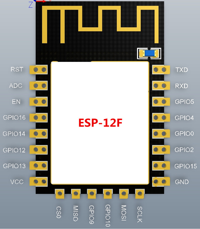
Pin-out:
ESP8266 is a 3.3V device. 5V will kill it!
If you plan to connect to 5V device such as an Arduino, be sure to use a logic level converter.
This modules breaks out a total of 22 pins - more pins than the others.
The wiring follows a typical serial connection. Connect Vcc to 3.3V and GND to ground. URXD to Tx pin and UTXD to Rx pin. In our test, CH_PD need to set to high (pull up to Vcc) in order for it to work.
Additionally, if you want to upgrade the firmware in the future, you have to pull down the GPIO0 to ground.
This module requires around 300 mA of current at its peak. If your microcontroller is not able to provide it, you might need an external power supply.


