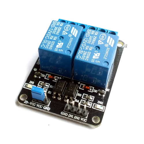
2-channel, 12V Relay module with Optocoupler
A relay can be used to control a high voltage device from your microcontroller/microcomputer (Raspberry Pi, Beaglebone Black, Arduino, PIC etc.).
This board has 2 active-low relays with each has a status indicator LED, an input pin to control the relay and three output terminals (normally open, normally closed and common terminal). Each relay is also opto-isolated. This means, there is no electrical connection between the high voltage device and the low voltage circuit that switching the relay. Therefore, it is much more safe and reduce the chances of accidently destroying the microcontroller that controlling the relay.
There are 2 sets of headers. The first set is 4-pin headers for controlling/triggering the relays. They are indicated on the PCB as IN1 and IN2 for input pin of each relay and GND and VCC pins. VCC is the module's voltage which gives logic HIGH. This can be connected to the 3.3V/5V pin of your system. The input pins (IN1/2) are to be connected to microcontroller/microprocessor signal pin. The relay is triggered when the input pin gets LOW signal.
The second set of headers has 3 pins for driving/powering the relays. They are marked as VCC, JD-VCC and GND. The JD-VCC pin is for the relay coil voltage. The board ships with a jumper over VCC and JD-VCC pins, shorting those two to give the same voltage for signalling and driving the relays. You'll need a 12V power source to reliably trigger the relay. Remove the jumper and connect 12V to the JD-VCC and GND.
Warning: Mains electricity can kill you. Please consult with a licensed electrician if you are working with the mains!
Features:
- 12V 2-channel relay board with optocoupler, each needs 15-20mA driving current
- SPDT type relay with one normally open terminal, one normally closed terminal and one common terminal
- Standard 2.54mm input header that can be controlled directly by microcontroller/microprocessor TTL logic (Raspberry Pi, BeagleBone Black, Arduino etc.)
- Screw terminals for relay contact
- 12V relay input signal voltage (Range: 0-12V)
- LOW on input pin will switch the relay
- VCC is module voltage, JD-VCC is relay voltage. VCC and JD-VCC are shorted by a jumper by default
- Relay contact capacity: 250V AC 10A or 30V DC 10A
- LED for state indicator for each relay
- Board dimension: 50mm x 40mm
- Mounting holes on the 4 corners of the board
