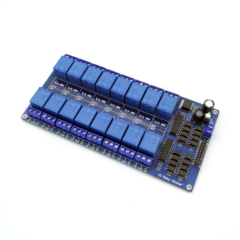
16-channel, 12V Relay module with Optocoupler
A relay can be used to control a high voltage device from your microcontroller/microcomputer (Raspberry Pi, Beaglebone Black, Arduino, PIC etc.).
This board has 16 active-low relays with each has a status indicator LED and three output terminals (normally open, normally closed and common terminal). Each relay is also opto-isolated. This means, there is no electrical connection between the high voltage device and the low voltage circuit that switching the relay. Therefore, it is much more safe and reduce the chances of accidentally destroying the microcontroller that controlling the relay.
There is a set of header with 10 x 2 rows of pins on the board for relay control. Pins labelled 1 to 16 is for trigger control of each corresponding relay. Since this is a LOW-level trigger module, pulling these pins low will trigger the relay. There are four extra pins, 2 pins give you 5V output and the other 2 pins are for Ground connection. You'll need a 12V power source for relay operation. This can be connected to the screw terminal labelled DC+ and DC-.
Warning: Mains electricity can kill you. Please consult with a licensed electrician if you are working with the mains!
Technical details:
- 12V 2-channel relay board with optocoupler, each needs 15-20mA driving current
- SPDT type relay with one normally open terminal, one normally closed terminal and one common terminal
- Screw terminals for working voltage (12V) labelled DC+ and DC-
- 12V relay input signal voltage (Range: 0-12V)
- Standard 2.54mm relay control header that can be triggered directly by microcontroller/microprocessor TTL logic (Raspberry Pi, BeagleBone Black, Arduino etc.)
- LOW on input pin will switch the relay (0-1.2V)
- Screw terminals for relay contact
- Relay contact capacity: 250V AC 10A or 30V DC 10A
- LED for state indicator for each relay
- Board dimension: 180 mm x 90 mm
- Mounting holes on the 4 corners of the board
